The focus of the project is looking at having two electric motors attached to a differential, so that if one should fail and lock up the other motor can actuate the system. This is a previous students project and I have been given an experimental rig that said student built.
Here it is...
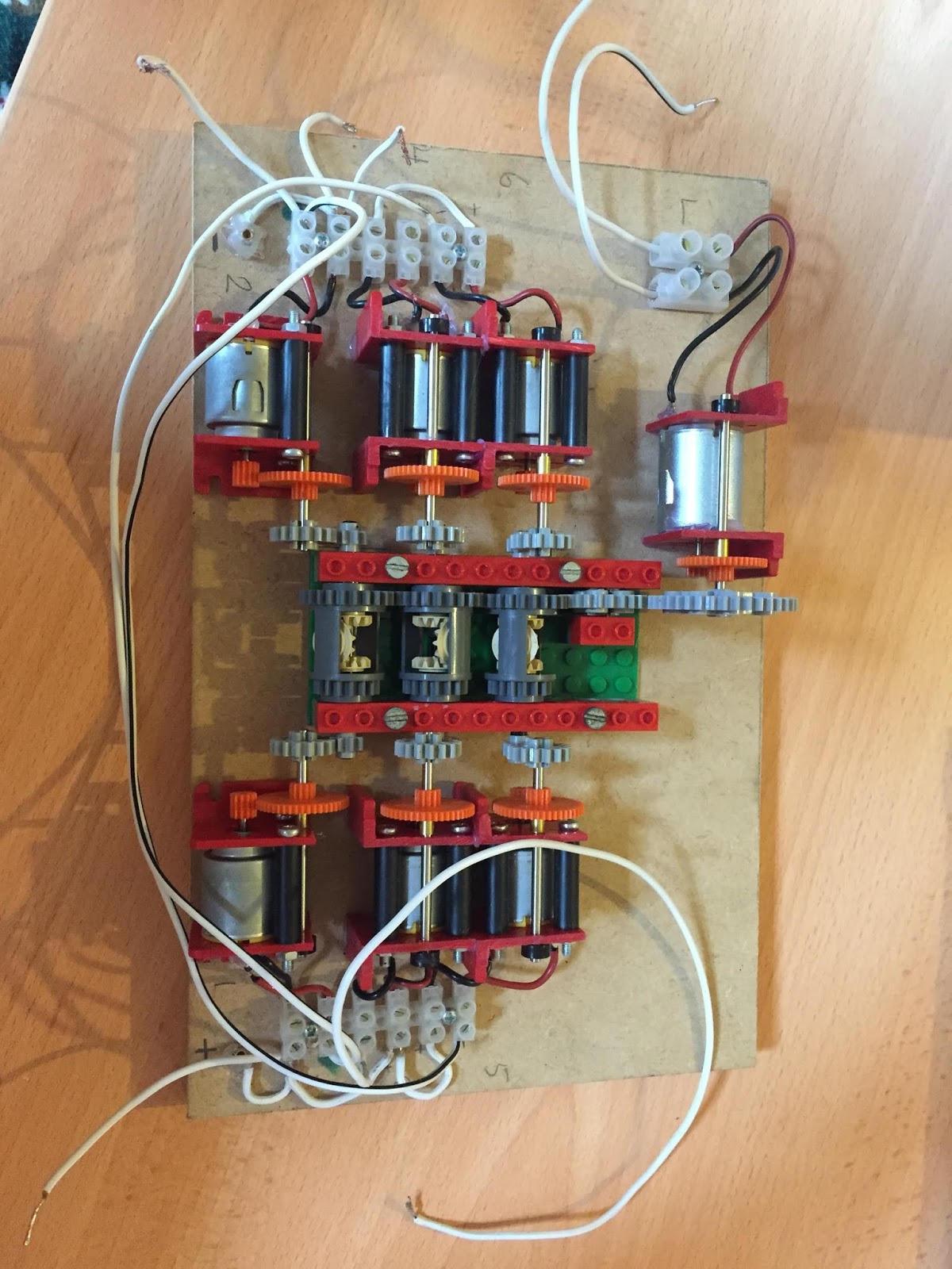
After I got it home and started playing with it I could see more wrong with it than right. So I decided to disconnect all of the wires and start fresh. The motors are all connected in parallel and they have a yellow circle at one end that denotes the orientation of each motor. See below.

The yellow circle has a flat edge this helped my decide which way round the motor is. If you swap the positive and negative over you change the direction of rotation simple.
It gets more complicated when you realise that the middle motor needs to be spinning in a different direction, also the other bank of motors all need to be spinning in the opposite direction because they have been glued in place upside down so the wiring appears to be the same on both sides. This would not be the case if the motors were all glued in the same way down.
Anyway the rig is up and running now and if you hold a motor still the system does keep on spinning just as planned. The previous student bought some RC car differentials to build the next level rig that will use harder gear trains and roller bearings to reduce friction.
One of the objectives in my project is to estimate the level of friction and and model this experiment and compare it to the actual experiment. I need to do some more reading on how to measure friction for a model.
Here is a pic of the finished board. Also the RC differntial that will make up the next rig.


I will next update with any literature I find on friction in gear trains and I also need to find a way to model the amount of energy the system is using. I know I have calculations for this in my notes I just need to search for it.
No comments:
Post a Comment