I have been researching some useful equations that I will use to theoretically model my DC Brushed motors. So far the equations have been pulled together from two separate groups of lecture notes and Electrical Machines, Charles Gross.
The inputs I will be recording into the system will be the current (I) and voltage (V), this will be from a power supply screen. I will use equation 1 to measure my value of k for my motors. I will require a speed sensor of some sort. Finding the change in motor speed over a known voltage change will give a value for k.
My motors are relatively slow and the power (P) is very small therefore I will use a simple DC Motor model as this will give reasonable accuracy, this gives equations 1 and 2.
Equations:
1. kw=V
2. kI=T
The k in both equations is called the motor constant. w is the angular velocity rad/s.
Force (F) generated by the motor is a product of the current, core length (l), number of coils (n) and magnetic flux density (B).
3. F=BIln
From equation 3 the torque can be calculated.
4. T=nIlBd
In equation 4 d denotes the perpendicular distance the force is generated from the axis of rotation.
Combining equations 4 and 2 to find a formula to give the motor constant.
5. kI=nIlBd ==> k=nlBd ==> k=nAB
A is the area of the windings. I will calculate my value of k using equation 5. I will compare this to my recorded value.
The equation for motor efficiency (E) is power input (Pin) divided by power output (Pout).
6. E=Pout/Pin x100
The equations for power are derived from the simple DC motor model.
7. Pout=Tw
8. Pin=VI
Therefore we can re-write the efficiency equation.
9. E=Tw/VI
This will give a theoretical efficiency of the motors. The next steps are finding the equations to model the dynamic inertia effects of the system along with all of the frictional losses.
More on this next post, for now I have more reading to do.
Tuesday, 20 October 2015
Monday, 19 October 2015
New vs. Current Motor Rig
An essential part of this project and of any engineering project is to record inputs and outputs to both systems and record the difference. Alot of the practical experimental work will be carried out after christmas, this semester I need to put together a test plan for both the old and new designs and a way of comparing the results.
The system has changed again, I recently had a meeting with my tutor and he urged me to get all of my ideas down into a few clear options and compare them. I should be looking at something that is achievable with the resources I have and also worth while doing.
We came to the conclusion that I should look at a way of measuring the current, voltages and speeds of both systems. Both systems should run the motors in pairs. In my last post I discussed the idea of having one motor powering a differential with a redundant motor waiting to be activated in case of a fault. This would not work, the differential would not transmit torque unless the redundant motor was locked.
This can be overcome by powering both ends of the differential, but have two redundant motors and a redundant differential all in case of a fault. This leads to an increase in the number of components which increases the probability of a fault however it will suffice for experimental purposes.
I have started reading Electric Machines by Charles Gross, the main piece of information I am looking for is an equation to describe the relationship between the Torque produced by a motor and the Current. Also the relationship between the speed and the voltage supplied.
Saturday, 10 October 2015
Motor Redundancy in a Model Rig
Part of my background reading for my Final Year Project FYP has lead me to a paper byMuenchhof, Beck, Isermann titled Fault Tolerant Actuators and Drive Structures, Fault Detection Principles and Applications within this paper its discusses fault tolerance along with fault detection methods.
The main objective of my project for me is to make a system that can accept a fault without a change in performance. This system would be implemented in a very critical system ie. and aeroplane or nuclear power plant. The actuators or motors in my system could be used for a valve in a pipe or wing flaps so it is really just an exercise to show one of the ways of producing a fault tolerant system.
The current arrangement of my system is to have two motors running constantly, if one should fail the system will continue with degraded performance.
I have been looking at redundancy within a system and it involves having back up parts that are activated when a fault is detected. In my system I could power one of the motors and have the other as a stand by. I could model a simple control system that will used a speed sensor to detect a 'lock up' type fault. This fault would trigger the other motor to start running the system.
The added advantages are simple the system would undergo no drop in performance should a fault occur, fault detection would be simple as a warning lamp or fault code could be integrated into the back up motor.
The obvious drawbacks are the differential arrangement gearing down the motor, and if the same motors are used it can lead to the common cause faults occurring in both. The fault be caused by adverse conditions like water or vibration that both of the motors would have to operate in.
I will look into similar spec motors that have different mounting or housing to prevent the common fault possibility.
I am yet to draw up a preliminary control system, I will probably do this under close guidance from my tutor as he is an expert in this field.
I have also started reading Blanke, Kinnaert, Lunze and Starowiecki Diagnosis and Fault Tolerant Control.
Thursday, 8 October 2015
Final Year project
To keep this blog active over my time at University I have decided to focus my blogs on my final year project. The title of my project is Fault Tolerant Rotary Actuation.
The focus of the project is looking at having two electric motors attached to a differential, so that if one should fail and lock up the other motor can actuate the system. This is a previous students project and I have been given an experimental rig that said student built.
Here it is...
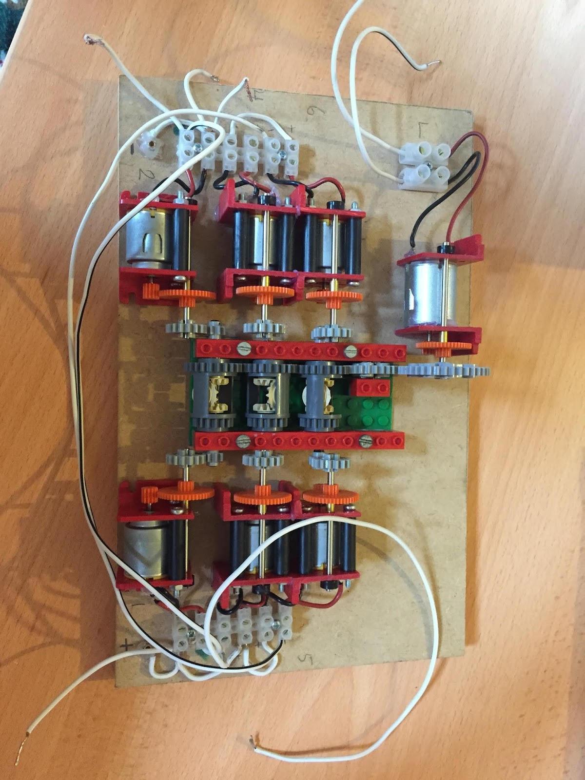
 It was a bit of a shambles there were wires everywhere and when I hooked it up to a power supply there was nothing, it is meant to spin up all of the six motors and their respective gear trains. The theory is that if you hold one of the motors still the main gears will all keep on moving just at a slower rate.
After I got it home and started playing with it I could see more wrong with it than right. So I decided to disconnect all of the wires and start fresh. The motors are all connected in parallel and they have a yellow circle at one end that denotes the orientation of each motor. See below.

The yellow circle has a flat edge this helped my decide which way round the motor is. If you swap the positive and negative over you change the direction of rotation simple.
It gets more complicated when you realise that the middle motor needs to be spinning in a different direction, also the other bank of motors all need to be spinning in the opposite direction because they have been glued in place upside down so the wiring appears to be the same on both sides. This would not be the case if the motors were all glued in the same way down.
Anyway the rig is up and running now and if you hold a motor still the system does keep on spinning just as planned. The previous student bought some RC car differentials to build the next level rig that will use harder gear trains and roller bearings to reduce friction.
One of the objectives in my project is to estimate the level of friction and and model this experiment and compare it to the actual experiment. I need to do some more reading on how to measure friction for a model.
Here is a pic of the finished board. Also the RC differntial that will make up the next rig.

 I tried to tidy up some of the wiring, I also added + - symbols to the MDF board to make it easier to identify wires in the future. The black and red colours do not denote charge of the wire.
I will next update with any literature I find on friction in gear trains and I also need to find a way to model the amount of energy the system is using. I know I have calculations for this in my notes I just need to search for it.
The focus of the project is looking at having two electric motors attached to a differential, so that if one should fail and lock up the other motor can actuate the system. This is a previous students project and I have been given an experimental rig that said student built.
Here it is...
After I got it home and started playing with it I could see more wrong with it than right. So I decided to disconnect all of the wires and start fresh. The motors are all connected in parallel and they have a yellow circle at one end that denotes the orientation of each motor. See below.

The yellow circle has a flat edge this helped my decide which way round the motor is. If you swap the positive and negative over you change the direction of rotation simple.
It gets more complicated when you realise that the middle motor needs to be spinning in a different direction, also the other bank of motors all need to be spinning in the opposite direction because they have been glued in place upside down so the wiring appears to be the same on both sides. This would not be the case if the motors were all glued in the same way down.
Anyway the rig is up and running now and if you hold a motor still the system does keep on spinning just as planned. The previous student bought some RC car differentials to build the next level rig that will use harder gear trains and roller bearings to reduce friction.
One of the objectives in my project is to estimate the level of friction and and model this experiment and compare it to the actual experiment. I need to do some more reading on how to measure friction for a model.
Here is a pic of the finished board. Also the RC differntial that will make up the next rig.


I will next update with any literature I find on friction in gear trains and I also need to find a way to model the amount of energy the system is using. I know I have calculations for this in my notes I just need to search for it.
Subscribe to:
Comments (Atom)