I have been researching some useful equations that I will use to theoretically model my DC Brushed motors. So far the equations have been pulled together from two separate groups of lecture notes and Electrical Machines, Charles Gross.
The inputs I will be recording into the system will be the current (I) and voltage (V), this will be from a power supply screen. I will use equation 1 to measure my value of k for my motors. I will require a speed sensor of some sort. Finding the change in motor speed over a known voltage change will give a value for k.
My motors are relatively slow and the power (P) is very small therefore I will use a simple DC Motor model as this will give reasonable accuracy, this gives equations 1 and 2.
Equations:
1. kw=V
2. kI=T
The k in both equations is called the motor constant. w is the angular velocity rad/s.
Force (F) generated by the motor is a product of the current, core length (l), number of coils (n) and magnetic flux density (B).
3. F=BIln
From equation 3 the torque can be calculated.
4. T=nIlBd
In equation 4 d denotes the perpendicular distance the force is generated from the axis of rotation.
Combining equations 4 and 2 to find a formula to give the motor constant.
5. kI=nIlBd ==> k=nlBd ==> k=nAB
A is the area of the windings. I will calculate my value of k using equation 5. I will compare this to my recorded value.
The equation for motor efficiency (E) is power input (Pin) divided by power output (Pout).
6. E=Pout/Pin x100
The equations for power are derived from the simple DC motor model.
7. Pout=Tw
8. Pin=VI
Therefore we can re-write the efficiency equation.
9. E=Tw/VI
This will give a theoretical efficiency of the motors. The next steps are finding the equations to model the dynamic inertia effects of the system along with all of the frictional losses.
More on this next post, for now I have more reading to do.
Tuesday, 20 October 2015
Monday, 19 October 2015
New vs. Current Motor Rig
An essential part of this project and of any engineering project is to record inputs and outputs to both systems and record the difference. Alot of the practical experimental work will be carried out after christmas, this semester I need to put together a test plan for both the old and new designs and a way of comparing the results.
The system has changed again, I recently had a meeting with my tutor and he urged me to get all of my ideas down into a few clear options and compare them. I should be looking at something that is achievable with the resources I have and also worth while doing.
We came to the conclusion that I should look at a way of measuring the current, voltages and speeds of both systems. Both systems should run the motors in pairs. In my last post I discussed the idea of having one motor powering a differential with a redundant motor waiting to be activated in case of a fault. This would not work, the differential would not transmit torque unless the redundant motor was locked.
This can be overcome by powering both ends of the differential, but have two redundant motors and a redundant differential all in case of a fault. This leads to an increase in the number of components which increases the probability of a fault however it will suffice for experimental purposes.
I have started reading Electric Machines by Charles Gross, the main piece of information I am looking for is an equation to describe the relationship between the Torque produced by a motor and the Current. Also the relationship between the speed and the voltage supplied.
Saturday, 10 October 2015
Motor Redundancy in a Model Rig
Part of my background reading for my Final Year Project FYP has lead me to a paper byMuenchhof, Beck, Isermann titled Fault Tolerant Actuators and Drive Structures, Fault Detection Principles and Applications within this paper its discusses fault tolerance along with fault detection methods.
The main objective of my project for me is to make a system that can accept a fault without a change in performance. This system would be implemented in a very critical system ie. and aeroplane or nuclear power plant. The actuators or motors in my system could be used for a valve in a pipe or wing flaps so it is really just an exercise to show one of the ways of producing a fault tolerant system.
The current arrangement of my system is to have two motors running constantly, if one should fail the system will continue with degraded performance.
I have been looking at redundancy within a system and it involves having back up parts that are activated when a fault is detected. In my system I could power one of the motors and have the other as a stand by. I could model a simple control system that will used a speed sensor to detect a 'lock up' type fault. This fault would trigger the other motor to start running the system.
The added advantages are simple the system would undergo no drop in performance should a fault occur, fault detection would be simple as a warning lamp or fault code could be integrated into the back up motor.
The obvious drawbacks are the differential arrangement gearing down the motor, and if the same motors are used it can lead to the common cause faults occurring in both. The fault be caused by adverse conditions like water or vibration that both of the motors would have to operate in.
I will look into similar spec motors that have different mounting or housing to prevent the common fault possibility.
I am yet to draw up a preliminary control system, I will probably do this under close guidance from my tutor as he is an expert in this field.
I have also started reading Blanke, Kinnaert, Lunze and Starowiecki Diagnosis and Fault Tolerant Control.
Thursday, 8 October 2015
Final Year project
To keep this blog active over my time at University I have decided to focus my blogs on my final year project. The title of my project is Fault Tolerant Rotary Actuation.
The focus of the project is looking at having two electric motors attached to a differential, so that if one should fail and lock up the other motor can actuate the system. This is a previous students project and I have been given an experimental rig that said student built.
Here it is...
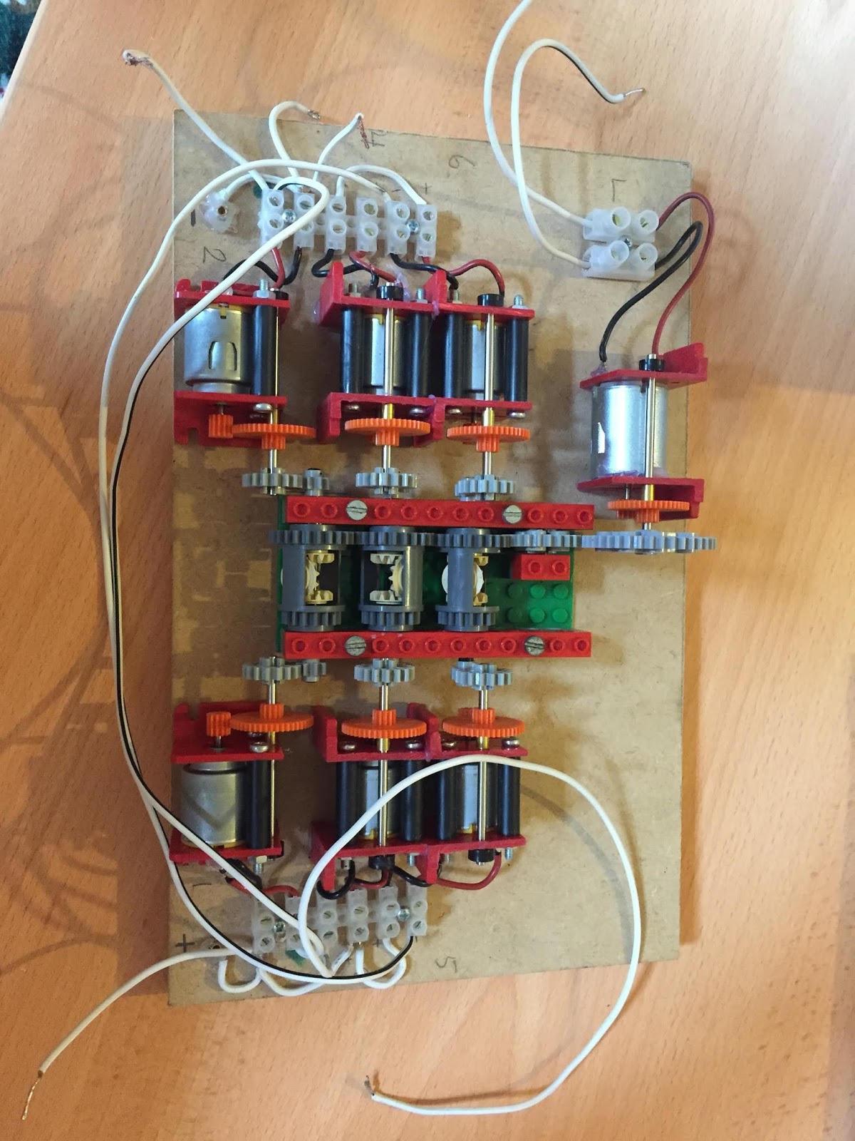
 It was a bit of a shambles there were wires everywhere and when I hooked it up to a power supply there was nothing, it is meant to spin up all of the six motors and their respective gear trains. The theory is that if you hold one of the motors still the main gears will all keep on moving just at a slower rate.
After I got it home and started playing with it I could see more wrong with it than right. So I decided to disconnect all of the wires and start fresh. The motors are all connected in parallel and they have a yellow circle at one end that denotes the orientation of each motor. See below.

The yellow circle has a flat edge this helped my decide which way round the motor is. If you swap the positive and negative over you change the direction of rotation simple.
It gets more complicated when you realise that the middle motor needs to be spinning in a different direction, also the other bank of motors all need to be spinning in the opposite direction because they have been glued in place upside down so the wiring appears to be the same on both sides. This would not be the case if the motors were all glued in the same way down.
Anyway the rig is up and running now and if you hold a motor still the system does keep on spinning just as planned. The previous student bought some RC car differentials to build the next level rig that will use harder gear trains and roller bearings to reduce friction.
One of the objectives in my project is to estimate the level of friction and and model this experiment and compare it to the actual experiment. I need to do some more reading on how to measure friction for a model.
Here is a pic of the finished board. Also the RC differntial that will make up the next rig.

 I tried to tidy up some of the wiring, I also added + - symbols to the MDF board to make it easier to identify wires in the future. The black and red colours do not denote charge of the wire.
I will next update with any literature I find on friction in gear trains and I also need to find a way to model the amount of energy the system is using. I know I have calculations for this in my notes I just need to search for it.
The focus of the project is looking at having two electric motors attached to a differential, so that if one should fail and lock up the other motor can actuate the system. This is a previous students project and I have been given an experimental rig that said student built.
Here it is...
After I got it home and started playing with it I could see more wrong with it than right. So I decided to disconnect all of the wires and start fresh. The motors are all connected in parallel and they have a yellow circle at one end that denotes the orientation of each motor. See below.

The yellow circle has a flat edge this helped my decide which way round the motor is. If you swap the positive and negative over you change the direction of rotation simple.
It gets more complicated when you realise that the middle motor needs to be spinning in a different direction, also the other bank of motors all need to be spinning in the opposite direction because they have been glued in place upside down so the wiring appears to be the same on both sides. This would not be the case if the motors were all glued in the same way down.
Anyway the rig is up and running now and if you hold a motor still the system does keep on spinning just as planned. The previous student bought some RC car differentials to build the next level rig that will use harder gear trains and roller bearings to reduce friction.
One of the objectives in my project is to estimate the level of friction and and model this experiment and compare it to the actual experiment. I need to do some more reading on how to measure friction for a model.
Here is a pic of the finished board. Also the RC differntial that will make up the next rig.


I will next update with any literature I find on friction in gear trains and I also need to find a way to model the amount of energy the system is using. I know I have calculations for this in my notes I just need to search for it.
Wednesday, 23 September 2015
Changing Fork Seals on a Honda Bros
I have a customer with a 89 400 Bros. It is is desperate need of some new fork seals. I have recently acquired some new tools for this job. This includes a depth syringe so the fork oil can be sucked out of the stanchion until it sits at an exact height. I did not end up using this I just poured in a desired quantity. I also bought a slide hammer to know down 41mm fork seals without causing any damage.
 Firstly I strapped down the rear end of the bike to raise the front wheel off of the bench.
 Pinch bolts need to be loosened before the axle can be un done.
 Caliper must be removed to get the wheel out. Then the fork brace and mudguard.
I always loosen the top clamp and then loosed the fork caps, keeping the lower stanchion tight so the fork doesn't just twist. Take care not to hit the tank like I did.


 Old and new seals.
 The upper most section of the stanchion has high levels of pitting, I use some plastic sheet to protect the ID of the seal from damage.


 I apply loctite the the allen bolt on assembly, the internals are just a simple clean and re-fit procedure nothing was changed this time.


I always loosen the top clamp and then loosed the fork caps, keeping the lower stanchion tight so the fork doesn't just twist. Take care not to hit the tank like I did.

The dust seal can be pried off with a chisel of wide flat head screw driver.

This will uncover a corroded C clip that slot into the fork slider. This is fairly easy to pry out using a small ended driver.

To separate the slider and stanchion the allen bolt in the bottom of the fork needs to be removed. This will be held in with loctite and so the slider should be mounted in a vice and then when an appropriate socket it fitted into the bolt it should be hit with a hammer to break the loctite's bond.

This should undo fairly easily. Then it is just a case of sliding the slider off of the stanchion, this will take a few attempts it takes a bit of force so dont be scared to really pull it off. Probably worth noting that once the allen bolt is removed fork oil should start leaking everywhere. So pop a bucket on the floor.

With the fork cap off also the internals can be removed. It is good practice to have a manual handy and to be mythodical. Its is easy to fit things the wrong way round.


I also make sure all of the seal are wet with fresh fork oil before assembly.

This slide hammer houses the oil seal nicely, it also pushes the new dust seal into place.


I annealed the washer to soften the copper and allow it to seal once again. This involves heating it up until you see a change in colour and letting it cool slowly. The forks were filled with fresh oil and re-fitted to the bike, the owner has notice a subtle but very pleasing improvement of the bikes ride and handling.
New Bikes mean New Problems
I have recently purchased a Honda Bros 650 1993 which is a later model bike with three spoke wheels and a PGM ignition. Its is exactly the same model as the other bros which I have blogged about before. The main difference is this bike is all mine which means I get full say in what modifications happen. The bike runs and rides ok the rear brake feels powerless however it has just had new pads so I will give it some time to bed in. Also the rear shock feels like it has a low spring rate the damping is adequate.
In order for me to ride the bike legally I have fitted two restrictor washers to the bike, they slip into the intake rubbers. I haven't found much difference in the performance except at full throttle.
To try and overcome the loss in power I have fitted two pod K&N filters, the bike revs up and down fine which would suggest the mixture was running rich as standard.
When a bike is running lean the main characteristic is the revs not dropping or dropping slowly once the throttle has been shut. The revs should drop almost immediately, the inertia of the engine prevents it happening instantly. Fitting pod filters means the bike will pull in more air per stroke so it tends to make your mixtures weak which is easily fixable with a bit of carb adjustment. Since my bike ran fine with pods it suggests the bike must of been a bit rich in the first place.
The characteristics of running rich are alot less noticable, it will show up as high hydrocarbons in an emissions analyzer. It also will give high fuel consumption, a build up of black soot around the exhaust and a black debris build up on the plugs. Its does normally give slightly more power and make the engine run cooler both of which are desirable.
 So I have just taxed, insured and MOT'd the bike. On my way home from the MOT station I noticed steam following me around. I decided to take it easy the rest of the journey by keeping the bike in the highest gear possible and keeping the revs below 3000rpm. This was to try and prevent the bike overheating I just needed to limp home and make an assessment as to where this steam (coolant) has come from.
 Alot of dirty coolant showered the bike. I started by looking at the thermostat, I notice a build up of white debris on the underside. This is a good indicator of a slow coolant leak.
 It seems pretty conclusive that the thermostat is at fault. It has three pipes, a breather and a pressure relief cap. Anyone of these could be at fault.
 There is only one stud of bolt that mounts the thermostat to the frame, a good tip would be to remove all of the clamps bfore removing the mounting screw.
 Problem found, the housing has two lugs on one side. One of mine has snapped off, it appears to have worn off I dont knwo how this could have happened but I have a spare thermostat and pipes so all is not lost.
 The pipes were blocked solid with dry coolant.
 The missing lug.


 The plug that sits below the thermostat is often neglected as it is a pain to remove. On the other bros three of the four plugs were new and this one looked like it has been pulled out of an ocean. On this bike it appeared to be much the same story. Coolant had leaked into the plug hole and corroded everything. I fitted new plugs with a smear of copper grease on the threads.
The plug cap fell off which is never good. There is just enough length on the HT lead to snip off the end section and screw into some fresh lead to gain some purchase. I used liberal amounts of wurth contact cleaner on both the lead and the screw within the cap to try and eat away at the blue corrosion that is common on electrical connections.
 I purchased some fresh ionised water to fill up the coolant system, I already have anti freeze knocking around so I poured it in roughly 50/50. Too much coolant and the bike will over heat, too much water and it could freeze and crack your casings!
 With the system filled I always lean the bike either side to try and get the last few bubbles out. I topped up the coolant tank and ran the bike up.
I changed the oil also its common practice with any new bike I buy. Just so I know the condition of it.
Bros tanks rub against their seats, its just the way it is. I cleaned the rust away to reveal the bare metal I treated the metal with Kurust this reacts with the steel and prevents any further rust from occurring. I covered this with some black acrylic paint just to cover it up a little.


 All covered up.
 After a polish the bike looked alright. I have since taken it for a spin and the coolant system is now water tight and working as it should. The bike sounds really smooth although you do get a bit more induction noise due to the pod filters. The bike handles really well and pulls like a train.
 Here are my Broses. I am immensely proud of these two bikes however the horizon is full of new ideas and potential for both of these bikes,
In order for me to ride the bike legally I have fitted two restrictor washers to the bike, they slip into the intake rubbers. I haven't found much difference in the performance except at full throttle.
To try and overcome the loss in power I have fitted two pod K&N filters, the bike revs up and down fine which would suggest the mixture was running rich as standard.
When a bike is running lean the main characteristic is the revs not dropping or dropping slowly once the throttle has been shut. The revs should drop almost immediately, the inertia of the engine prevents it happening instantly. Fitting pod filters means the bike will pull in more air per stroke so it tends to make your mixtures weak which is easily fixable with a bit of carb adjustment. Since my bike ran fine with pods it suggests the bike must of been a bit rich in the first place.
The characteristics of running rich are alot less noticable, it will show up as high hydrocarbons in an emissions analyzer. It also will give high fuel consumption, a build up of black soot around the exhaust and a black debris build up on the plugs. Its does normally give slightly more power and make the engine run cooler both of which are desirable.


The replacement thermostat was in one of the boxes of spares we have collected over time. It had new looking pipes so I decided to fit these also.


The plug cap fell off which is never good. There is just enough length on the HT lead to snip off the end section and screw into some fresh lead to gain some purchase. I used liberal amounts of wurth contact cleaner on both the lead and the screw within the cap to try and eat away at the blue corrosion that is common on electrical connections.


I changed the oil also its common practice with any new bike I buy. Just so I know the condition of it.
Bros tanks rub against their seats, its just the way it is. I cleaned the rust away to reveal the bare metal I treated the metal with Kurust this reacts with the steel and prevents any further rust from occurring. I covered this with some black acrylic paint just to cover it up a little.


Fabricating a Subframe for the New Seat Unit
A huge milestone in the EXUP build was receiving the seat unit from Ragged Edge Racing (website below) the service was second to none and I could not recommend them more. My seat unit arrived with a small dent in it. After sending images to ragged edge I was given an immediate refund in full for substandard work. The dent is repairable with a bit of rubbing down and filler so it was a win win for me.
raggededgeracing.com
I need to fabricate a subframe to mount this seat unit, for the lines of the bike to flow into the seat unit I needed the top of the seat unit to run inline with the top of the tank. I also need to ensure the seat unit is far back enough so I fit on the bike im on the healthy side of 6"2.
 I used an existing subframe as a base. I set about chopping the lower braces off and swapping them over so the left is now on the right and vice versa. This has narrowed the underside of the frame whilst still allowing just enough room to fit in the battery box. The packaging under this seat unit will be very tight but will dramatically improve the looks of the bike.

 These braces were roughly marked out and cut off, I used a grinding wheel to cut the edges into a semi circle so they sit flush with the bar they will eventually be welded to.
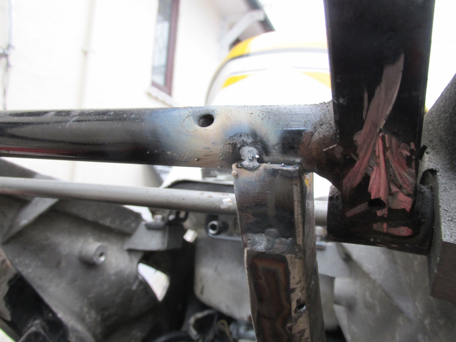
 I managed to rest the subframe in place, thankfully it seemed to fit well so I decided to go ahead with tacking it up before welding it completely.


 I am using a gas-less MIG welder which is only good for tacking if in honest, my TIG welder is out of action so I had to complete the job by constantly cleaning off the slag and re tacking until there was effectively a seam of weld.

 I regularly offered up the seat unit to ensure the subframe gave me the desired angle, not too much but just enough to fit with the existing lines of the bike.
 I really want the top of the seat unit and the top of the tank to flow smoothly, the overall look for this bike is effectively a retro track day/cafe racer which is a bit strange but I think it will make a refreshing change from the streetfighter treatment these bikes are far too often victim to.
 A small amount of frame had to be ground off to make clearance for the lower subframe struts.
 These lugs were initailly used as a seat support for the standard plastic seat unit, I decided to drill and tap them through so I could mount a bar across the bike to eventually mount the seat unit off. I decided to drill straight down this turned out to be a terrible idea, I should have kept all of the hole perpendicular to the surface.

 I was pretty happy with this bar, I am yet to find a safe and robust way of mounting the seat unit, I know I will have to measure it up and drill the seat unit first. However I need a little more time to find a solution. Time is ticking as I will be back at university within a week.


 much cleaner lines compared to the standard seat unit which always made the bike look saggy and slow. This new clearance between the tyre and the seat really gives the bike a purposeful and aggressive stance.

raggededgeracing.com
I need to fabricate a subframe to mount this seat unit, for the lines of the bike to flow into the seat unit I needed the top of the seat unit to run inline with the top of the tank. I also need to ensure the seat unit is far back enough so I fit on the bike im on the healthy side of 6"2.


I know nothing to be proud of but it will suffice for the application.


And this is why. I offered up a piece of box section however the bolt head and mounting surface were at an angle and soI had to fabricate an angle in the box section to take up this mis alignment of the mounting surfaces.


Here are some images to give an overview of the desired look of the seat unit.


Subscribe to:
Comments (Atom)